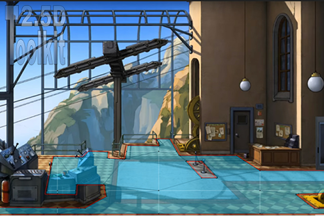
Essential knowledge
First of All
2.5dTK requires:
- The AI Navigation package installed and active in your project.
- Gizmos enabled in Game View to correctly visualize walkable areas and editor tools.
- A correct character height set in the attached NavMeshAgent component, as it affects movement, scaling, and camera behaviour.
Testing and Previewing Your Scene
At any time during scene creation, you can test your work in Play Mode or perform a Build for a more accurate preview.
If you are using the Background Camera, you must select the aspect ratio that matches your background image.
If your scene uses scrolling with a Background Sprite, you can freely change the aspect ratio and resolution from the editor, obtaining a perfect preview for every supported screen format.
Baking the NavMesh
For maximum baking reliability while building your scene and testing different camera settings, set the Radius to the lowest practical value (typically 0.05).
Once your work is complete, you can increase the Radius until all walkable areas are baked correctly.
Note:
A small Radius helps both the legacy Unity Navigation system and the newer AI Navigation package generate cleaner, more accurate NavMesh borders. Larger values can cause gaps, overlaps, or missed surfaces, especially in tight or complex areas.
Recommended workflow:
Bake with a minimal Radius during development, then gradually raise it at the end of the process until you achieve the desired walkable surface.
Horizon line
In Perspective Projection, the position of the yellow horizon line changes according to the camera settings (its Y position, rotation) and the FOV.
2.5D Toolkit enforces minimum and maximum limits for these parameters.
The horizon line must never intersect walkable areas or scene objects, otherwise those elements would move incorrectly as the projection updates.
If you reach one of these limits, keep in mind the following relationships:
- Increasing the FOV lowers the horizon.
- Decreasing the FOV raises the horizon.
- Increasing the rotation raises the horizon.
- Decreasing the rotation lowers the horizon.
This means that if you need to decrease the rotation but areas or objects in the scene prevent the horizon from moving down, you can simply lower the FOV first, which will raise the horizon.
Once the horizon is high enough, you can safely decrease the rotation.
The same principle applies to all combinations of FOV and rotation adjustments.
Mouse functions
Note:
To draw, you do not need to hold the left mouse button.
Creating areas
- Left click
- Drawing: insert a new vertex.
- Over spot (vertex): select to move.
- Right click
- Drawing: show/hide tracking line.
- Over area edge: insert a new vertex.
- Middle click
- Over spot (vertex): remove spot.
- Double click
- Over area edge: select area.
- Outside area edge: deselect area.
Creating environment
- Left click
- [Tab Scene]: (with meter setting enabled) Over area edge: show / hide length.
- [Tab Objects]: move object (while holding the button down, drags it).
- Right click
- [Different tab]: Move character (while holding the button down, drags it).
- [Tab Navigation/New Slope]: Over spot: select spot.
- [Tab Navigation/Select Spot] Over spot: select spot.
Spot and Line Radius settings
These settings are very important, and you should keep an eye on them whenever you significantly change your camera parameters.
When you hover the cursor over an area, it highlights.
Double-clicking one of its edges makes that area active.
When you hover over a spot, it also highlights and can be selected.
These settings define the minimum distance required for area edges or vertices to react to mouseover.
They may behave differently depending on whether you are working in the Game View or the Scene View.
For optimal results, keep these ranges large enough to ensure comfortable selection, but make sure that when you hover over a vertex, the neighboring one does not highlight.
If two spots light up at the same time and you perform an action such as moving or deleting a vertex, the operation may not affect the intended one.
Initialize GameObjects in scene
To initialize objects, they must be dragged into their corresponding fields from the Project folder.
This is required because each object will be adapted to the needs of 2.5dTK.
For sprites, a Sphere Collider and an object management script will be added automatically, enabling full control through the toolkit’s tools.
For the character, the script will automatically assign the necessary control and motion scripts based on the projection mode and the preferences you set.
Once an object has been created and configured, you must manage it by dragging it from the Hierarchy into the appropriate fields.
Dragging the same object from the Project folder instead will create new independent copies.
Create mesh
To create a mesh, drag VBAreaTK (the child object of 2.5dTK) into the Area field and click Create mesh.
The option Don’t destroy on save lets you choose whether to keep the generated mesh in your scene or not.
All created meshes are stored in:
2.5d ToolKit/25dTKTools/Scene data/[scene name]/Mesh
Note:
Dragging the main VBAreaTK will generate a single merged mesh containing all drawn areas.
Alternatively, you can create individual meshes by dragging each area separately.
Big sprites
Using big sprites allows you to work much more easily and quickly than using standard (small) sprites.
These sprites have the exact same size as the background image, and you can create them directly with the built-in Sprite Editor.
When you move a big sprite, it will always cover the exact portion of the background image it was cropped from, regardless of where you place the cursor.
You don’t need to adjust X or Y positions; placement is based solely on the Z axis, making the process immediate and precise.
Watch this video to learn more about creating and placing big sprites:
v2 03 – 2.5D Toolkit: A way to place sprites with just a click in one second
Tips
Camera
A 2.5D environment generally does not require a high FOV.
Many background images also require camera rotation, and a high FOV combined with rotation can introduce noticeable character distortion near the edges of the screen.
To reduce the perceived depth of the scene, increase the camera rotation (while considering the space in which the character moves).
If your scene contains more than one level or includes game objects, camera settings become locked.
Define all camera parameters while working on the base level (the base level may contain multiple areas), and add game objects only after the environment is fully completed.
Note:
Adjusting FOV and rotation also affects the position of the horizon line. If you reach a limit because of areas or objects in the scene, modify one parameter temporarily to unlock the other.
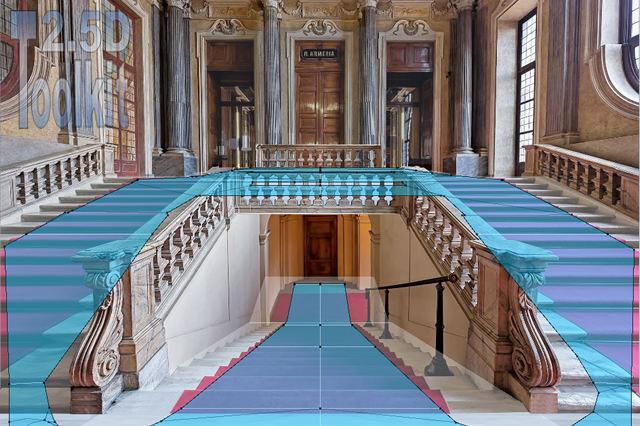
Scene
In perspective projection, use the meter function together with the recommended step count suggested by the script to achieve a realistic environment.
For reference, a single step typically covers 65–80 centimeters.
If the character travels 10 meters with 15 steps, we divide 10 by 0.70 and obtain approximately 14, which is within the expected range.
If the calculated number of steps falls within the suggested interval, your scene proportions are correct.
If it falls outside that range, it is advisable to adjust the camera settings and try again.
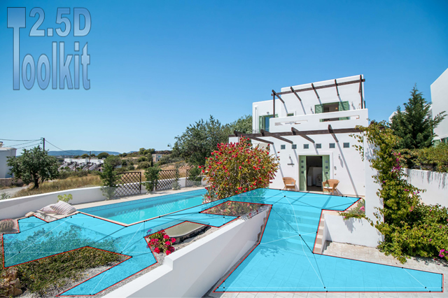
Areas
When creating areas, make sure that the vertices or edges of one area do not touch those of another.